
Company News
Methods and operations of universal testing machine
Release time:2018-11-23 source:Jinan Hengsi Shanda Instrument Co., Ltd. Browse:
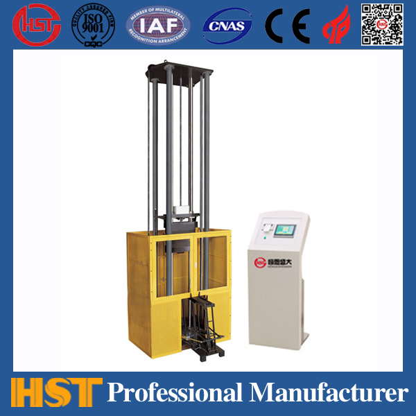
Use of electro-hydraulic servo universal testing machine
The electro-hydraulic servo universal test machine is a high-precision and high-tech product that combines machine, electricity and liquid. Reasonable use and maintenance can not only ensure the fault-free operation of the equipment, but also extend the service life of the equipment and give full play to the economic benefits of the equipment.
1. Use a suitable fixture to complete the corresponding test, otherwise the test will not be very successful, but it will also damage the fixture: the electro-hydraulic servo universal test machine is generally only equipped with fixtures for making standard samples. If you want to make non-standard samples, such as steel strands, overlapping steel fines, etc., you must add appropriate fixtures; there are also some super hard materials, such as spring steel, and clips of special materials must be used, otherwise the fixtures will be damaged;
2. Cleaning and cleaning: During the test, some dust will inevitably be produced, such as oxide scales, metal debris, etc. If it is not cleaned in time, it will not only cause wear and scratches on the surface of certain parts, but more serious consequences will be caused if these dusts enter the hydraulic system, blocking the valve holes and scratching the piston surface. Therefore, cleaning after each use is very critical, and the test machine must be kept clean;
3. Hydraulic oil: The fluid level of the oil tank must be checked frequently and replenished in time; generally, oil must be changed every 2000 to 4000 hours of use; however, it is important that the oil temperature must not exceed 70℃, and the cooling system must be turned on when the oil temperature exceeds 60℃;
4. Filter: For filters without clogging indicators, they are generally replaced every 6 months. For filters with clogging indicators, continuous monitoring should be carried out and must be replaced immediately after the indicator alarms;
5. Accumulator: Some electro-hydraulic servo universal testing machines are equipped with accumulators, so the pressure of the accumulator must be ensured to be in a normal working state. If the pressure is found to be insufficient, the pressure needs to be replenished immediately; only nitrogen is allowed to be charged to the accumulator;
6. Regular inspection of components: All pressure control valves, flow control valves, pump regulators, and signal devices such as pressure relays, stroke switches, thermal relays must be regularly inspected;
7. Cooler: The scale accumulation of air-cooled coolers should be cleaned regularly; if water-cooled coolers are used, they should be regularly observed for the cooling copper pipe to be cracked and leaked;
8. The lead screw and transmission parts should be regularly coated with lubricating oil to prevent dry friction;
9. Fasteners must be locked regularly: the vibration after the sample is broken will often loosen some fasteners. It is necessary to inspect regularly to avoid major losses caused by loose fasteners.
10. Other inspections: Be vigilant and pay close attention to details, so that signs of accidents can be detected early and prevent major accidents. This is especially true when the equipment is initially put into operation. Always pay attention to external leakage, contaminants, component damage, and abnormal noise from pumps, couplings, etc.
I hope that the above proposal will bring some benefits to the normal use of your electro-hydraulic servo universal testing machine.
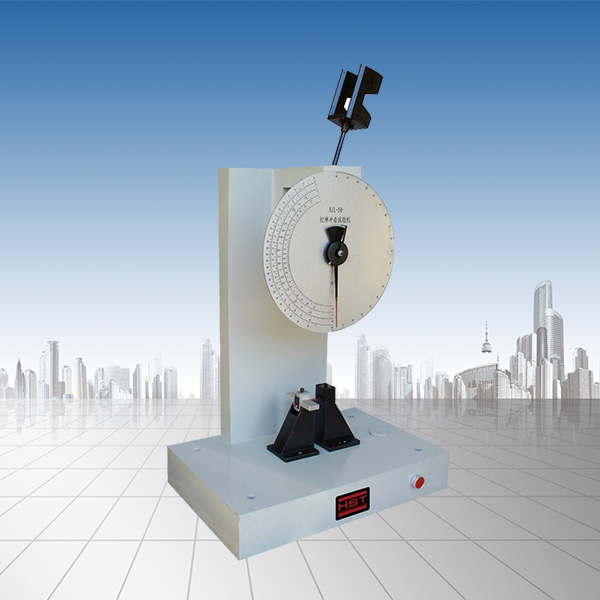
How to use hydraulic universal testing machine
1. Test operating procedures
1. Turn the main switch on the power supply.
2. According to the sample, select the measurement range, hang or remove the swing thallium on the swing rod and adjust the buffer valve handle to align the standard line. 3. Install the corresponding chuck into the upper and lower jaw seats according to the shape and size of the sample.
4. On the drum of the depictor, roll the recording paper (graph paper), which is only done when necessary.
5. Turn on the oil pump motor, unscrew the oil feed valve to make the test stand raise paper 10 mm, and then close the oil valve. If the test stand is already in the raised position, there is no need to turn on the oil pump first, just close the oil feed valve.
6. Clip one end of the sample into the upper jaw.
7. Turn on the oil pump adjustment point to the zero point of the accuracy dial.
8. Turn on the lower jaw motor, lift and lower the lower jaw to an appropriate height, clamp the other end of the sample into the lower jaw, and be careful to make the sample perpendicular.
9. Put down the drawing pen on the push rod and enter the drawing ready state (it is done only when it is required).
10. Slowly unscrew the oil feed valve according to the loading speed required by the test.
11. Close the oil valve after the sample is broken and stop the oil pump motor.
12. Record the required values and will be depicted.
13. Open the oil return valve and turn the passive needle back to zero after unloading.
14. Remove the broken sample.
15. The above tests can be carried out in accordance with the above items.
2. Installation, initial operation, maintenance and other
1. Installation
The test machine should be installed in a clean, dry and uniform house, and the possibility of long beam bending tests on the machine and the possibility of using a mirror extension gauge for testing, so sufficient spare area should be left around the test machine. When installing the main body of the test machine and the dynamometer, there is no need for special foundations. Only the general foundation is made according to the foundation map and the anchor screw holes are left to be poured. To find the level of the main body of the test machine, you can place the level on the outer circle of the oil cylinder and find the level according to the longitudinal and horizontal positions of the machine base and the horizontal direction. Use a level with an accuracy of 0.10/1000 mm to find ±1 grid, and add a shim under the base to adjust it when it is not normal. There are two holes on the top of the dynamometer for wire rope when reinstalling. The level of the dynamometer is very important. When finding the level, the left side of the swing rod is aligned with the markings of the standard line plate to keep it still. Then use a curved ruler to lean on the large surface of the upper part of the swing rod and place it on the curved ruler with a level of 0.1/1000 mm to find ±2 grids. If it is incorrect, add a shim under the base, and the oscillating thallium and the pointer must be fixed at zero point. Open the iron door above the dynamometer and check whether the wire hammer is wound in the groove of the pointer coaxial pinion. The length of the wire rope should be appropriate, not too long or too short. The limit is long and cannot be touched on the evacuation partition. Remember to remember to the cross-divider. If the pinion rotates for one round, the aging hammer will not touch the pinion.
2. Take over
When installing the oil pipe with the main body and the dynamometer, the oil pipe should be washed with diesel first, so that no impurities are left in the pipe to ensure the cleanliness of the oil circuit. Pay attention to whether the joint washer is complete. If it is incomplete, use the new washer included in this machine to prevent oil leakage during high pressure.
3. Introduction to the specifications of oil
High-quality medium viscosity mineral oil should be used in hydraulic transmission. The oil must contain no water, acid and other mixtures, and should not decompose or thicken at ordinary temperatures. The oil must be filtered before pouring into the machine. Due to improper oil use, the valve and oil circuit will be blocked and the machine may vibrate, which will affect the normal operation of the test machine. Reference specifications of oil: Specific gravity: 0.86-0.97 Freezing point: -15℃ to -20℃ According to actual conditions, domestically produced No. 30-50 engine oil can also be used.
4. Fill and drain oil
Open the iron door on the left side of the dynamometer and you can see the wire mesh oil filter. When filling the oil, it is injected into the oil tank through this oil filter. The amount of oil poured in at one time is about 28 liters. The oil level indicator installed on the outside of the oil tank shall prevail. The oil specifications used can be found in the introduction to the specification selection of the oil. Before starting to use the test machine, the movable bolt installed from the oil tank to the oil pump pipeline must be opened. When the movable bolt is in line with the pipe, it means that the oil circuit between the oil tank and the oil pump is unobstructed. If the movable bolt is orthogonal to the pipe, it means that it is closed. When draining oil, just open the oil nozzle at the bottom of the left side of the dynamometer. The service life of the oil is determined according to the climate in various places. If you find that the oil is filthy and cannot be used, you should replace it with new oil. If you want to wipe the bottom of the oil tank or when you drop in and out, put the oil clean first. Remove the round cover at the bottom of the left side of the dynamometer. You must put it in after completion.
5. Connect to power
The electrical device of this test machine is equipped with a dynamometer, with a magnetic starter that can be operated by buttons, and a small transformer, the input power supply is 380 volts, the output voltage is 6 volts, and a 6.3 volt small indicator light is provided on the upper right side of the front of the dynamometer. The power supply of this test machine is 380 volts, and the magnetic starter coil is 380 volts. The wires brought from the power supply are connected to the terminal board through the front cover of the dynamometer. All wiring can be used to refer to the electrical circuit included in this manual. Connect the power supply and turn on the passage bolt between the oil tank and the oil pump. After the other parts have completed inspection, they can turn on the buttons on the dynamometer table to try to run the oil pump motor to observe whether the direction of the flywheel rotation is consistent with the direction of the flywheel arrow. If it does not match, the power connector should be changed to make it consistent. Then, turn on the lower jaw seat lifting motor to check whether the lifting action of the lower jaw seat is consistent with the text shown on the button, and then check whether the overpass and overcharge buttons are used.
6. Lubrication
There is an oil injection hole on the pressure gland above the base of the main body. The nut is lubricated through the hole. The threads of the screws for lifting and lowering of the lower jaw seat should be lubricated frequently according to the use to avoid wear and hinder rotation. After the main body is installed, use a funnel to inject engine oil into the oil tank through the seat hole of the oil probe needle on the base. The injected oil depth is 30 mm, and it is measured with the oil probe needle. Ball bearings at both ends of the spindle inside the dynamometer are not allowed to be oiled and lubricated to avoid the generation of sludge over time hindering the sensitivity of the precise mechanism. If the internal is disassembled for a long time, you can rinse the ignition oil and put in a very small amount of high-quality lubricating oil, but it must be enough to prevent it from rusting. After installing it, a standard dynamometer will be re-calibrated. There is no screw block on the oil pump. After installation, unscrew it when used first and inject a large amount of oil into the oil pump. In the future, if the internal oil is not used for a long time, the screw blocked under the oil pump can be opened and refilled. If the machine is frequently used, it should be replaced approximately once a month.
7. The initial operation and test drive of the oil pump
Press the button on the dynamometer table to start and stop the rotation of the oil pump. When the wire connector is first operated or changed after installation, it is necessary to check whether the movable bolt leading to the oil pump passage of the oil tank is opened and whether the rotation direction of the oil pump pulley after it is started is rotated in the direction indicated by the arrow. For the first operation after installing the oil pump, first remove the screws on the top of the oil pump to fill the same oil as in the oil tank with an oil pot in the wire hole. After filling, tighten the screws. If you find that the internal engine oil is not used for a long time, you can plug the screws under the oil pump and open it, and then refille the clean oil. If you use it normally every day, it is more appropriate to pump it once a month. When the oil pump is first running, there is often a small part of the air inside the oil pump that cannot be discharged or in some cases air is sucked into the oil pump, and the output of the oil will be intermittent, so the increase in load will be irregular, and the pointer will cause intermittent phenomenon. In order to judge this phenomenon, the side cover of the dynamometer can be removed to observe. If there is no throbbing in the oil supply valve, it can be imagined that the oil pump is working normally. Due to the presence of air, the oil pump outputs oil.
Recommended productsPRODUCTS