Company News
Simple maintenance of steel strand tester
Release time:2018-11-23 source:Jinan Hengsi Shanda Instrument Co., Ltd. Browse:
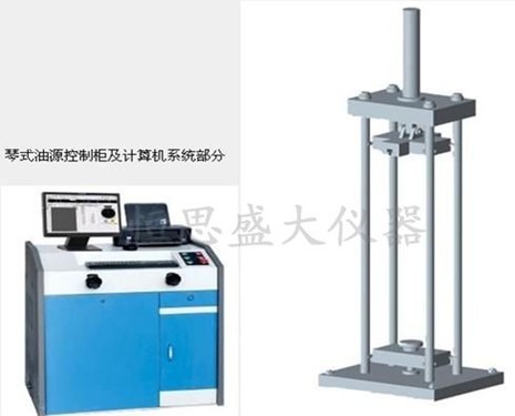
6.1.2.1 Hardware composition, oil source host
6.2 Daily maintenance
6.2.1 All parts of the test machine should be wiped clean frequently. Wipe the surface without paint cleanly and apply cotton yarn to a small amount of engine oil to wipe it again to prevent rust. Pay attention to wiping during the rainy season. When not in use, cover it with a dust cover to prevent dust from invading.
6.2.2 All shutters on the control cabinet should not be opened and placed to prevent dust from entering the interior, affecting the sensitivity of the measurement mechanism.
6.2.3 Long-term frequent use may lead to a decrease or deterioration of the oil. The amount of oil should be checked every 1-3 months according to the use situation. After the equipment is stopped for 15 minutes, observe the oil window on the left side of the control cabinet. If the oil surface is lower than the oil window, add the same hydraulic oil to the middle of the oil window; if the oil has deteriorated, new hydraulic oil must be replaced.
6.2.4 Frequent use of this equipment for tensile breaking tests may cause some fasteners to loosen. The following areas should be checked frequently:
a. There are two (8 pieces in total) L block pressing plates in front and behind the upper beam and the moving beam (which acts as a guide for the jaw clamping plate), each pressing plate is fixed with 2 screws;
b. Move 6 screws at both ends of the crossbeam;
c. Check the tightness of the screw drive chain every 6 months, and adjust the position of the tightening wheel accordingly (it needs to be removed after the lower fence of the main body);
d. Check the tightness of the oil pump transmission belt once a year and make corresponding adjustments (can be done after opening the lower valve of the control cabinet).
4.2.5 According to environmental conditions and frequency of use, lubricate the following parts every 3 to 6 months:
a. The joint of the screw and the base are lubricated with No. 100 oil;
b. The screw drive chain is lubricated with butter;
c. The screw part of the screw remains clean and lubricated with butter or molybdenum disulfide;
The lubrication of both places of ab requires removal of the lower fence of the main body.
6.2.6 There are two jaw clamps for installing jaws on the upper cross beam and the mobile cross beam. They are important parts of this machine. The debris on the contact surfaces between the jaw clamps and the beam should be frequently removed according to the use situation to avoid lashing the contact surface. The method is: remove the press plate on one side of the moving beam, take out the jaw clamp, use an oil rag to clean the contact surfaces of the jaw clamp and the beam, apply an appropriate amount of butter and graphite mixed grease, replace the jaw clamp and tighten the fixing screws of the press plate.
6.3 Use of hydraulic clamping mechanism
a. Connect the rubber hoses according to the attached figure seven, A1-A1', B1-B1', A2-A2', B2-B2', C-C', D-D', E-E'.
b. The GWE-1000B/600B lower hydraulic universal machine adopts a hydraulic clamping mechanism, and the magnetic movement control box consists of six buttons: upper clamping, upper loosening, lower clamping, lower loosening, jaw lifting, jaw lowering, etc.
c. Adjust the working pressure of the overflow valve. The overflow valve is located under the integrated block of the force measuring machine. The adjusting handle can make the upper and lower clamping pistons move, the smaller the pressure, the better.
d. High pressure rubber hose size:
4+4A1-A1' hose 5×3300mm
5+5B1-B1' hose 5×3300mm
6+6A2-A2' hose 5×2800mm
7+7B2-B2' hose 5×2800mm
3+3C-C' hose 12×1000mm
2+2D-D' hose 12×1000mm
1+1E-E' hose 12×1000mm
7. Troubleshooting
IFault phenomenon: There is abnormal noise and vibration in the oil supply valve.
Possible reasons: The oil temperature is too high or the oil temperature is too high due to the high temperature or the long-term continuous operation, which makes the oil viscosity smaller.
Corresponding exclusion method: Add appropriate amount of hydraulic oil with high viscosity (such as N100 oil) to temporarily shut down and wait for the oil temperature to drop before continuing to work.
II Fault phenomenon: The test machine cannot meet the rated test force.
Possible reasons:
a. The oil supply valve has foreign object blockage;
b. There is leakage in the hydraulic system.
Corresponding exclusion methods:
a. Remove the cleaning oil supply valve. If the valve core has woven hair, you can grind the bud paste until it is smooth.
b. Tighten or replace new gaskets at the oil leakage.
III Fault phenomenon: The jaw slips during stretching.
Possible reasons: The scale or iron chips on the sample fall into the sliding surface between the jaw plate and the beam, causing the bite or the resistance to increase.
Exclusion method: Remove the jaw clamp and grind the strained area on the sliding surface with a file, and apply a blending agent of graphite and butter.
Ⅳ Failure phenomenon: The moving beam is not lifted smoothly.
Possible reasons for troubleshooting electrical faults:
a. There is insufficient lubrication between the screw rod and the base hole or foreign objects block the jam;
b. The locking screws of the lower nut of the screw rod are loose.
Corresponding exclusion methods:
a. Remove the lower nut of the screw rod, start the oil pump, use the piston to push the screw rod out about 150 mm, clean, add lubricating oil, and install;
b. Check and reinstall the screw lock.
- Previous article:Understand the impact test machine
- Next article:Electro-hydraulic servo improves precision testing performance for testing machines
Recommended productsPRODUCTS


