
Company News
About the construction and working principle of hydraulic swing universal testing mechanism
Release time:2018-11-23 source:Jinan Hengsi Shanda Instrument Co., Ltd. Browse:
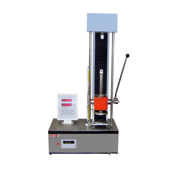
Hydraulic swing type universal test machineIt is generally composed of two parts: applying force and measuring force, and its structural principle is shown in Figure 5.2.
1. The force-applied part of the universal material testing machine
On the machine base 1, two fixed columns 2 are installed, which support the fixed cross head 3 and the working cylinder 4 . After the motor starts up, the motor drives the oil pump 5 to work, and feeds the oil from the oil tank through the oil supply pipe and the oil supply valve 23 into the working oil cylinder 4, thereby pushing the working piston 6 , the upper cross head 7 , the movable column 8 and the movable table 9 upwards. If both ends of the tensile sample are clamped in the upper chuck 10 and the lower chuck 11, the lower chuck is fixed and the sample will bear the tension when the movable table rises. When clamping and stretching the sample, the lower chuck motor or hand-crank device can be used to rotate the worm gear in the base to lift and lower the stud 13 to an appropriate height. The compressed sample is placed between the upper and lower pad plates 12, and the sample is subjected to pressure when the movable table rises to the contact of the sample and the upper pad plate. The oil feed valve in the oil pipeline is used to control the amount of oil inlet into the working oil cylinder to adjust the velocity of the pressure to the sample. When the oil return valve 24 is applied, the oil return valve 24 is placed in the closed position. When the oil return is opened, the oil in the working oil cylinder can be discharged back to the oil tank, and the movable table will drop due to its own weight and return to its original position.
2. The force measurement part of the universal material testing machine
The force exerted by the sample is generated by the hydraulic pressure in the working cylinder 4 pushing the working piston 6 . The force measuring cylinder 14 is connected to the working oil cylinder 4 by a force measuring oil pipe, and this oil pressure pushes the force measuring piston 15 downward, causing the pull rod to push the pendulum 16 to rotate about the fulcrum and lift it. At the same time, the swinging upper push rod pushes the tooth rod 17 to rotate the gear and pointer 18 . The angle of rotation of the pointer is proportional to the oil pressure, that is, to the force of the sample, so the magnitude of the pressure of the sample can be read from the pointer on the measuring force disc 19. If the weight of the pendulum is different, the oil pressure required for the pointer to rotate at the same angle is also different, and the magnitude of the force shown by the pointer is related to the weight of the pendulum. Generally, there are three types of heavy hammers in the test machine, called A, B, and c from small to large, where A is fixed, B and c are disassembled, and are used to measure the three ranges of A (low gear), A+B (middle gear), and A+B+C (high gear) shown on the velocity dial.
There are generally automatic drawing devices on universal material testing machines. When the movable table rises, the pulley can be used to drive the roller to rotate by a pulley fixed to one end to the movable table. The circular movement of the roller indicates the deformation of the test piece; at the same time, the axial movement of the tooth rod driving the rotation shaft of the gear and the force measuring pointer indicates the force; the drawing pen fixed to the tooth rod qualitatively automatically draws the force on the coordinate paper of the cylinder surface of the roller.变形关系曲线。
http://www.hssdtest.com/
Recommended productsPRODUCTS