Company News
Introduction to the expert of hydraulic universal testing machine
Release time:2018-11-23 source:Jinan Hengsi Shanda Instrument Co., Ltd. Browse:
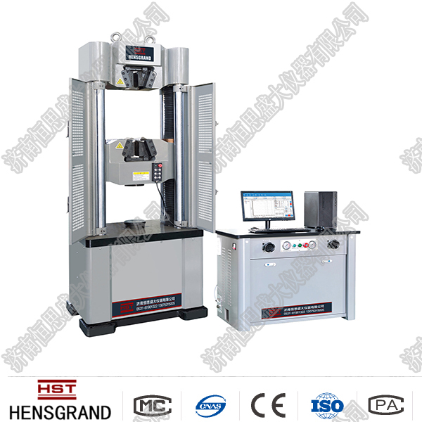
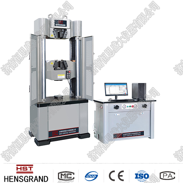
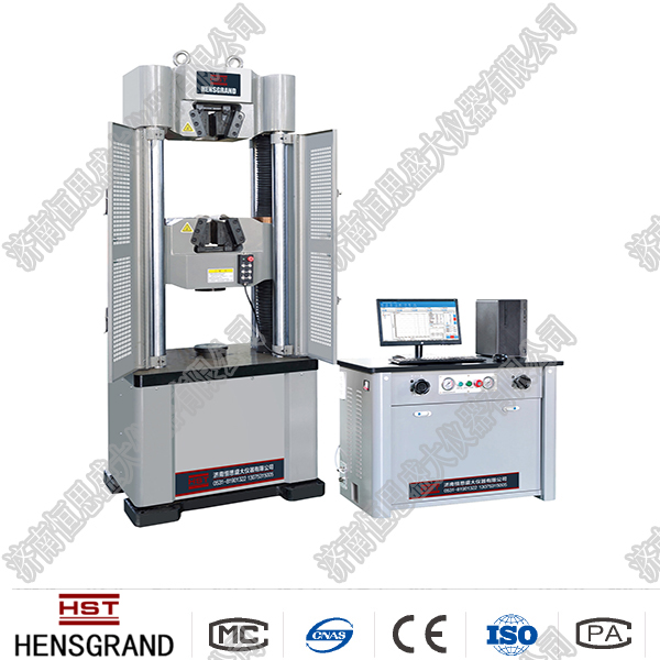
The main equipment for determining the mechanical properties of a material is a material testing machine. Commonly used material testing machines include tensile testing machines, pressure testing machines, torsion testing machines, impact testing machines, fatigue testing machines, etc. A test machine that can double-use a variety of experiments such as tensile, compression, shear, and bending is called a universal test machine. According to the nature of the afterburner, it can be divided into static load test machines and dynamic load test machines. Universal material testing machines for static experiments include hydraulic, mechanical, electronic and other types. The following will focus on these three types of universal testing machines.
1. Loading system
The bearing frame is composed of two fixed columns and fixed beams on the base. The working cylinder is fixed to the frame. On the working piston of the working cylinder, a movable frame consisting of upper beams, movable columns and movable platform is supported. When the oil pump is started, the oil passes through the oil supply valve and enters the working oil cylinder through the oil supply pipe, and lifts up the working piston and the movable platform. In this way, if the sample is installed between the upper chuck and the lower chuck, the upper chuck will rise with the movable platform and the sample will be stretched. If the sample is placed between two pressure-bearing pads, or the bent sample is placed on two bent supports, the movable platform rises due to the stationary beam not moving, and the sample will be compressed or bent respectively. In addition, if you want to adjust the distance between the upper and lower chucks before the experiment begins, you can start the position adjustment motor and drive the screw to make the lower chuck rise or fall. However, the position adjustment motor cannot be used to apply tension to the sample.
2. Force measurement system
When loading, start the oil pump motor, open the oil supply valve, and the oil pump sends the oil into the working oil cylinder and lifts the working piston to load the sample; at the same time, the oil enters the force measurement cylinder through the return oil pipe and the force measurement oil pipe (the oil return valve is closed at this time, and the oil cannot flow back to the oil tank), presses the force measurement piston and drives the pull rod to move downward, thereby forcing the swing rod and the pendulum to deflect about the fulcrum point together with the push rod. When the push rod deflects, the gear rod is pushed to move horizontally, so the pointer gear of the indices disk is driven to rotate the indices about the center of the indices disk. The angle of rotation of the force indicator is proportional to the total pressure on the force cylinder piston (i.e. the tension force applied to the pull rod). Because the oil pressure in the force measuring cylinder and the working cylinder is the same, the total pressure on the pistons of the two cylinders is proportional (the ratio of piston area). In this way, the angle of the force pointer is proportional to the total pressure on the working cylinder piston, that is, the load on the sample. After calibration, the pointer can directly indicate the load magnitude on the indicator dial.
The test machine is generally equipped with pendulums of different weights and is available. For pendulums with different weights, the hydraulic pressure required is not the same, that is, the load is not the same. Therefore, the force range indicated by the scale on the display dial should match the weight of the pendulum. Taking the WE-300 test machine as an example, it is equipped with three pendulums: A, B, and C. The force measurement range corresponding to the pendulum A is 0~60kN, A+B corresponds to 0~150kN, and A+B+C corresponds to 0~300kN.
When starting the oil pump motor, the size of the oil supply valve can adjust the speed of the oil entering the working oil cylinder, so it can be used to control the speed of increasing load. Opening the oil return valve can cause the oil in the working oil cylinder to be discharged back to the oil tank through the return pipe, thereby removing the load on the sample.
Before the experiment begins, in order to eliminate the influence of the self-weight of the movable frame, the oil should be activated to pump oil and raise the movable platform by about 10mm. Then adjust the balance thallium of the force measuring part to keep the swing rod vertically and make the force pointer point at zero point.
There are usually automatic drawing devices on the test machine. Its working principle is that when the movable platform rises, the pulley is driven to rotate the drum about the axis by a pulley, and a coordinate representing displacement along the circumferential line is formed on the cylinder surface of the drum; at the same time, the movement of the tooth rod constitutes a coordinate representing load along the axis of the drum. In this way, the drawing pen can automatically draw the load-displacement curve on the roller during the experiment. Of course, this is just a qualitative curve, not very accurate.
3. Operating procedures and precautions
1. Estimate the load according to the sample size and material, and select the corresponding velocity dial and pendulum weight. When automatic drawing is required, the paper and pen on the roller should be loaded in advance.
2. First close the oil supply valve and oil return valve, and then start the oil pump motor. After the oil pump is working properly, open the oil supply valve and raise the movable platform by about 10mm to eliminate its own weight. Then close the oil supply valve, install the sample, and adjust the indicator dial pointer so that it points at zero point.
3. When installing the tensile sample, the position adjustment motor 3 can be turned on to adjust the position of the lower chuck. After the sample is installed, the position adjustment motor cannot be started again.
4. Slowly open the oil supply valve to load the sample smoothly. The oil valve should be avoided from opening too much and injecting oil too quickly. During the experiment, be careful not to touch the swing rod or pendulum.
5. After the experiment is completed, close the oil supply valve and stop the oil pump from working. In the destructive experiment, first remove the sample, then slowly open the oil return valve and put the oil back into the oil tank. In non-destructive experiments, the oil return valve should be opened first before the sample should be removed.
- Previous article:Mechanical universal testing machine
- Next article:Extension meter
Recommended productsPRODUCTS


