Company News
Mechanical universal testing machine
Release time:2018-11-23 source:Jinan Hengsi Shanda Instrument Co., Ltd. Browse:
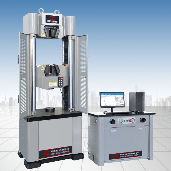
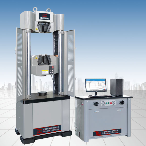
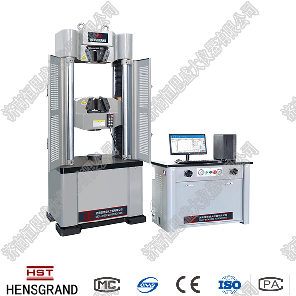
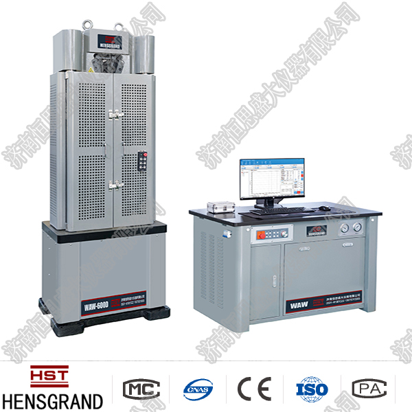
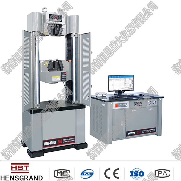
The mechanical universal testing machine is a special equipment that relies on mechanical transmission and force measurement. This testing machine can also perform tensile, compression, bending, shear and other tests.
1. Loading system
The load-bearing fixing frame is composed of a base, two fixed columns and an upper cross head. A movable table is installed in the middle of the frame, and experiments such as stretching, compression, bending, and shearing can be performed separately in the upper space of the movable table. This test machine can be loaded with electric and hand cycling devices respectively. When loading with electric power, first place the clutch handle in the "slow" position, then turn on the motor and drive the turbo worm in the base to rotate through the continuously variable transmission. The movable table and the lower chuck are driven to move downward or upward along the guide rail by a screw. The specimen is clamped between the upper chuck and the lower chuck. The movable table moves downward to stretch the sample and moves upward to compress the sample. The loading speed can be adjusted by rotating the handwheel. The marked value on the handwheel refers to the movement speed of the lower chuck, and its speed range is 5 to 30 mm/min. Note that the loading speed can be adjusted through the handwheel only when the motor is running. In order to prevent the handwheel from being rotated casually, the handwheel should be clamped with a locking handle to avoid damaging the machine parts. When manual slow loading is required, adjust the clutch handle to the "manual" position, and shake the handle 7 to move the lower chuck. If it is necessary to quickly adjust the distance between the upper and lower chucks, the clutch handle must be adjusted to the "fast" position first. At this time, the motor and the small motor work at the same time, which drive the screw 5 to rotate faster, thereby causing the lower chuck to move quickly. Two points to note when turning on a small motor: It has very small power and can only run without load. Second, when it is very fast, you should pay attention to shutting down the machine in time to prevent the upper and lower chucks from colliding and damaging the motor.
2. Force measurement system
The specimen is installed between the upper and lower chucks, and the load is transmitted through the two-stage lever systems of AB and CE, which drives the pendulum to rotate and lift around the fulcrum. The AB lever has two fulcrums. When the sample is tensed, A is used as the fulcrum and B is disengaged; when the sample is compressed, B is automatically disengaged and point A is disengaged. Therefore, whether the sample is tensioned or compressed, the CE lever is consistent, the pendulum always swings in one direction, pushing the horizontal tooth rod 22 to move, and the tension or pressure magnitude that the specimen is subjected to can be read on the display dial. The pendulums of this kind of test machine are divided into three types: A, B, and C. For 100KN test machines, the corresponding force measurement ranges are 0-20kN, 0-50kN, and 0-100kN respectively. The weight of the upper chuck and lever system is balanced by the balanced thallium. Before the experiment begins, adjust the balance thallium to keep the swing rod vertical, and the force point is directed to the zero point. Due to the structural characteristics of this kind of test machine, the zero point is not easy to change, so there is no need to adjust the zero point frequently.
3. Operation steps and precautions
1. Prepare the corresponding test piece chuck according to the requirements. Check that the clutch, speed control handwheel and relevant cut-offs are in the correct position.
2. Estimate the required load, select the velocity measurement dial, and configure the corresponding pendulum. Adjust the vertical swing rod and adjust the zero point of the pointer.
3. Install the sample. If the distance between the chuck is not appropriate, you must turn on the machine to adjust the movable table to the appropriate position, and then clamp the sample after shutting down. For tensile tests, the upper and lower chucks must be tightened.
4. Adjust and install the drawing system, pen and paper, etc.
5. Formal test loading:
Manual loading: First place the clutch handle in the "manual" position, then shake the handle to load.
Electric Loading: To place the clutch handle in the "slow" position, then start the motor loading. If necessary, the speed control handwheel can be used to change the load speed.
6. After the experiment is completed, shut down immediately. Remove the test piece and everything is restored.
7. Notes:
1) In order to make the clutch gear mesh well, while adjusting the clutch handle to the "manual" position, turn the manual load handle.
2) The speed control handwheel must be rotated under the condition of the loading motor to achieve electric loading and speed control.
3) To change the running direction of the motor, the machine must be shut down first and then reversed.
4) When the test machine is running, the operator shall not leave without authorization, shall not touch the pendulum, there shall be abnormal phenomena or any failure, and the machine must be stopped immediately.
5) Small motors can only be used to quickly adjust the lifting of the movable table, and are strictly prohibited for loading or unloading.
- Previous article:Introduction to the universal electronic test machine
- Next article:Introduction to the expert of hydraulic universal testing machine
Recommended productsPRODUCTS


