
Company News
Maintenance of steel strand tester
Release time:2018-11-23 source:Jinan Hengsi Shanda Instrument Co., Ltd. Browse:
1. Main Overview
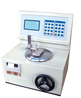
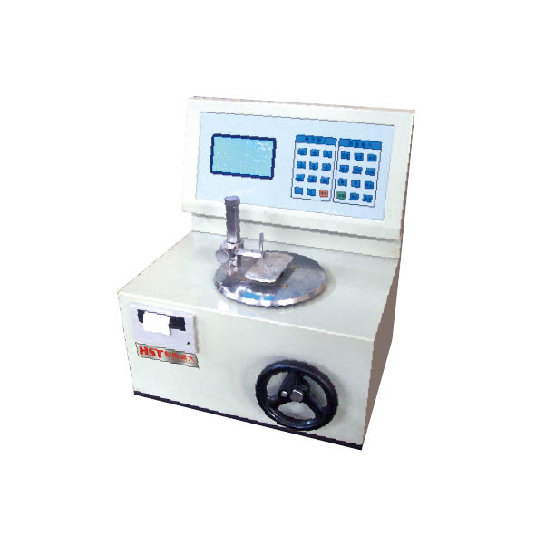
The GWE series microcomputer control universal testing machine adopts the microcomputer control electro-hydraulic servo valve loading and manual hydraulic loading, and the main body and control frame are separated. It has the characteristics of convenient operation, stable and reliable work, high test accuracy and stable after-force, and is suitable for tensile, compression, bending and shear tests of metals, cement, concrete, plastics and other materials.
It is recommended to install and use this equipment in an environment that meets the following conditions:
a. Clean, dry, no vibration, and there is space for testing and maintenance (≥0.7m);
b. Room temperature is 10℃-35℃.
Product specifications and main technical indicators are shown in the attached table.
2. Host structure principle
2.1 Principles of mechanical structure
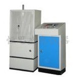
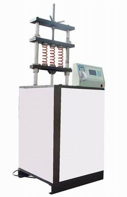
The main part of this equipment is composed of a height-adjustable support frame [composed of a machine base, a screw and a moving crossbeam (lower jaw seat)] and a working frame [composed of a working oil cylinder, piston, platen, bracket and upper crossbeam (uper jaw seat)]. Its working principle is: the high-pressure oil pump supplies oil to the working oil cylinder, and the piston moves, pushes the platen and upper beam (upper jaw seat) upwards, and performs tensile or compression tests of the sample. The tensile test is performed between the upper beam and the moving beam of the main machine, and the compression test is performed between the platen of the main machine and the moving beam of the main machine. The adjustment of the test space is achieved by driving the double screws to rotate simultaneously by driving the driving mechanism (lifting motor, sprocket, chain, etc.).
2.2 Electrical Principles
This equipment uses three-phase 380V and 50Hz AC power supply. The main circuit includes an oil pump motor and a lift motor. A fuse is connected to the main circuit and the control circuit respectively to prevent excessive current. A thermal relay is also connected in series in front of the oil pump motor and the lift motor to prevent overloading of the motor.
3. Installation
3.1 Unboxing and acceptance
After you unbox, please check the quantity of equipment and accessories based on the order contract and packing list and check whether it is complete. If you find a shortage or damage, please notify the company as soon as possible for timely handling.
3.2 Preparation before installation
The test machine should be installed in a room with a clean, dry, no vibration and room temperature between 10℃-35℃. Enough space (≥0.7m) should be left around the test machine for testing and maintenance.
The main body and control cabinet of the test machine should be installed on a concrete foundation. The foundation size is based on the appearance and foundation map, and the base screws and other wire installation pipes are left to adjust the upper plane of the foundation.
3.3 Preliminary correction of the installation accuracy of the test machine
Preliminary body correction: Use a frame level or borrow a wire hammer in the accessory to correct the perpendicularity of the column in two directions perpendicular to each other, and adjust it by inserting small iron sheets at the bottom of the body. Hang the anchor screws.
Use cement mortar to solidify the screws of each foot, fill the gaps between the tester and the ground, and maintain them for a week.
3.4 Connection of hydraulic system
a. Remove the bundles in each part and clean the inside of the oil pipe with clean kerosene.
b. Check whether the gasket at the joint is complete. If it is damaged due to transportation reasons, use the new gasket included in this machine to prevent oil leakage during high pressure.
c. Use a suitable wrench to connect each oil pipe.
d. This equipment usually uses N68 anti-wear hydraulic oil. When the ambient temperature is too high, N100 hydraulic oil is added to increase the viscosity according to the situation.
3.5 Electrical installation
The power supply voltage of this equipment is 380V in three phases, and the equipment must be grounded. The electrical connection between the main body and the control cabinet is made of plugs. Before powering on, open the iron door of the control cabinet to check whether it is falling off at all connections, whether the fuse is loose, and remove dust and debris in the electrical box. After confirming that the equipment has been connected to the power supply line, press the lifting action of the jaw seat under the "Power" on the control counter panel to match the text shown on the button. If the opposite is true, change any two phase lines; unscrew the oil feed valve and raise the piston, refer to the ruler on the main column to check whether the piston stroke limit switch is in effect; then close the oil feed valve after slightly raising the working piston.
3.6 Debugging
3.6.1 Start the oil pump and repeatedly raise the piston. Exhaust the air in the oil cylinder and oil pipes. It can be observed that the return oil is continuous and stable.
If you find that the pointer is stagnant in a certain range during the pressure test, perform the following operations:
a. Select the range, adjust the working pressure to half of the range and stabilize.
b. Open the iron door of the control cabinet, rotate the exhaust wire on the right side of the outer circle of the oil supply valve, and then rotate it back.
*c. When performing the above operations, you must pay attention to: ① The working pressure should not be too high; ② The force should be light and slow when the exhaust wire is blocked and rotated, and be careful not to break it.
3.6.2 Test drive
a. Pull the cold-bending support to both sides equally, and do not touch it when moving the cross beams up and down;
b. Install spherical lower pressing plate on the table plate, lift and move the cross beam so that the upper and lower pressing plates are about 20mm apart;
c. Select the full range, start the oil pump, close the oil return valve, open the oil supply valve to increase the plate, and slowly increase the pressure to 80% of the range;
d. Check the zero return error and check whether there is any oil leakage at each oil pipe joint;
e. If there is oil leakage, tighten the connector after unloading the force.
4. Operation
4.1 The operation of the entire machine must be used in conjunction with the control cabinet measurement and control system, see 6 for details
4.2 Daily maintenance
4.2.1 All parts of the test machine should be wiped clean frequently. Wipe the surface without paint cleanly and apply cotton yarn to a small amount of engine oil to wipe it again to prevent rust. Pay attention to wiping during the rainy season. When not in use, cover it with a dust cover to prevent dust from invading.
4.2.2 All shutters on the control cabinet should not be opened and placed to prevent dust from entering the interior, affecting the sensitivity of the measurement mechanism.
4.2.3 Long-term frequent use may lead to a decrease or deterioration of the oil. The oil volume should be checked every 1-3 months according to the use situation. After the equipment is stopped for 15 minutes, observe the oil window on the left side of the control cabinet. If the oil surface is lower than the oil window, add the same hydraulic oil to the middle of the oil window; if the oil has deteriorated, new hydraulic oil must be replaced.
4.2.4 Frequent use of this equipment for tensile breaking tests may cause some fasteners to loosen. The following areas should be checked frequently:
a. There are two (8 pieces in total) L block pressing plates in front and behind the upper beam and the moving beam (which acts as a guide for the jaw clamping plate), each pressing plate is fixed with 2 screws;
b. Move 6 screws at both ends of the crossbeam;
c. Check the tightness of the screw drive chain every 6 months, and adjust the position of the tightening wheel accordingly (it needs to be removed after the lower fence of the main body);
d. Check the tightness of the oil pump transmission belt once a year and make corresponding adjustments (can be done after opening the lower valve of the control cabinet).
4.2.5 According to environmental conditions and frequency of use, lubricate the following parts every 3 to 6 months:
a. The joint of the screw and the base are lubricated with No. 100 oil;
b. The screw drive chain is lubricated with butter;
c. The screw part of the screw remains clean and lubricated with butter or molybdenum disulfide;
The lubrication of both places of ab requires removal of the lower fence of the main body.
4.2.6 There are two jaw clamps for installing jaws on the upper cross beam and the moving cross beam. They are important parts of this machine. The debris on the contact surfaces between the jaw clamps and the beam should be frequently removed according to the use situation to avoid lashing the contact surface. The method is: remove the press plate on one side of the moving beam, take out the jaw clamp, use an oil rag to clean the contact surfaces of the jaw clamp and the beam, apply an appropriate amount of butter and graphite mixed grease, replace the jaw clamp and tighten the fixing screws of the press plate.
- Previous article:Testing machines and test machines commonly used in English
- Next article:How to use the spring tension test machine